Archive for the ‘inversor eléctrico’ Category
A. Azizi, M. Z. Jahromi, P. Dehghanian, H. R. Chamorro, J. Mírez and V. K. Sood, «Decentralized Multi-Objective Energy Management With Dynamic Power Electronic Converters and Demand Response Constraints,» in IEEE Access, vol. 11, pp. 146297-146312, 2023, doi: 10.1109/ACCESS.2023.3344209. keywords: {Costs;Energy management;Renewable energy sources;Power system dynamics;Voltage;Power system stability;Optimization;Demand response;Dynamic generation;demand response;renewable energy;optimization;energy management;microgrid},
https://ieeexplore.ieee.org/document/10364854

Dr. Jorge Luis Mírez Tarrillo
Group of Mathematical Modeling and Numerical Simulation (GMMNS). Universidad Nacional de Ingeniería. Lima, Perú.
E-mail: jmirez@uni.edu.pe
Website Personal: https://jorgemirez2002.wixsite.com/jorgemirez
Facebook http://www.facebook.com/jorgemirezperu
Linkedin https://www.linkedin.com/in/jorge-luis-mirez-tarrillo-94918423/
Scopus ID: https://www.scopus.com/authid/detail.uri?authorId=56488109800
Google Scholar: https://scholar.google.com/citations?user=_dSpp4YAAAAJ
MATLAB Group Admin in Facebook: https://www.facebook.com/groups/Matlab.Simulink.for.All
Videoconferencia sobre Vehículos Eléctricos en la red y un resumen de tecnologías de generación distribuida en el marco de Energías Renovables. . Invitados a darle Me Gusta ![]() a mi fanpage http://www.facebook.com/jorgemirezperu. Transmisión en vivo y en directo. Compartir
a mi fanpage http://www.facebook.com/jorgemirezperu. Transmisión en vivo y en directo. Compartir ![]()
«Design and construction of a single-phase cascade multi-level inverter prototype». David Sarzosa, Jorge Mírez. Perfiles. Edition Nº 17 Vol.1 – [January – June 2017].
Available in: http://ceaa.espoch.edu.ec:8080/revista.perfiles/Articuloshtml/Perfiles17Art3/Perfiles17Art3.xhtml

«Simulation of DC Microgrid and Study of Power and Battery Charge/Discharge Management». Jorge Mírez, Luis Hernández-Callejo, Manfred Horn, Luis Miguel Bonilla. DYNA Ingeniería e Industrial. November 2017 – Volume: 92 – Pages: 673-679.
DOI: http://dx.doi.org/10.6036/8475

PERU Green Smart Energy S.A.C. es una empresa peruana que se dedica al rubro de bienes y servicios en temas de ingeniería, energias renovables, expedientes técnicos, material audiovisual – publicitario y de capacitación, expedientes técnicos en ingenierias, arquitectura, ciencias de la salud, entre otros. También nos dedicamos a la investigación científica, cálculos técnicos y capacitación.
Gustoso de pertenecer a la familia de PGSE S.A.C. en donde doy toda mi experiencia y conocimientos.
Para más información, consultas y coordinaciones sobre los bienes y servicios que ofrecemos, visita nuestra página web:
Pronto comenzaremos con nuestras capacitaciones virtuales (en español) con certificación. Lo estaremos promocionando con tiempo, pero les recomendamos ser nuestros seguidores dándole click en Me Gusta ![]() de nuestro fanpage para mantenerse informado de las novedades
de nuestro fanpage para mantenerse informado de las novedades
Fanpage de PGSE S.A.C. (darle Me Gusta):
http://www.facebook.com/PeruGreenSmartEnergySAC
Atentamente:
Jorge Luis Mírez Tarrillo
Ing. Mecánico Electricista – MSc & Dr. Física.
https://jmirez.wordpress.com
http://jmirezmedical.wordpress.com
Hoy jueves 27 diciembre 2018 recibí el Diploma de Doctor en Ciencias mención Física por la Universidad Nacional de Ingeniería, Lima, Perú. // Today, Thursday, December 27, 2018, I received the Diploma of Doctor of Sciences with mention in Physics (Dr. Physics) from the National University of Engineering, Lima, Peru.
Algunas fotos // some photos:

Recibiendo el diploma en Oficina de Grados y Títulos de la Universidad Nacional de Ingeniería, Lima, Perú. // Receiving a diploma in the Office of Degrees of the National University of Engineering, Lima, Peru.

En frente al Rectorado de la Universidad Nacional de Ingeniería, Lima, Perú // In front of the Rector’s Office of the National University of Engineering, Lima, Perú.

Con mi asesor Dr. Manfred Horn (a mi co-asesor Dr. Josep Guerrero en la Universidad de Aalborg, Dinamarca, muchas gracias también) // With my advisor Dr. Manfred Horn (a my co-advisor Dr. Josep Guerrero at the University of Aalborg, Denmark, thank you very much too) //
De mi fanpage // of my Fanpage:
Gracias a todos… A quienes estuvieron, están y/o estarán en este camino… Gracias por su espera, paciencia, enseñanzas, cariño, alegrías… estas cosas no se logran de la noche a la mañana… Queda aún algunos años para devolver lo recibido de la vida… Hoy jueves 27 Diciembre 2018 recibí el diploma de Doctor en Ciencias con mención en Física y al igual que mis grados y títulos anteriores me fue entregado en Ventanilla de una Oficina de Grados y Títulos y está bien, porque todos somos capaces, todos somos seres humanos… // Thank you all … Those who were, are and / or will be on this path … Thank you for your wait, patience, teachings, affection, joys … these things are not achieved overnight … There are still some years to return the received of life … Today, Thursday, December 27, 2018, I received a Doctor of Science degree with a mention in Physics and, like my previous degrees and diplomas, it was delivered to me in the Office of Degrees and Titles and that’s fine, because we’re all capable, we’re all human beings …. Fuente/Source: http://www.facebook.com/jorgemirezperu
Email: jmirez@uni.edu.pe
Invitación a Defensa de Tesis: «CONTROL, OPTIMIZACION Y GESTIÓN DE MICRORREDES DE CORRIENTE CONTINUA» para optar el Grado Académico de Doctor en Ciencias con mención en Física. Elaborado por Jorge Luis Mírez Tarrillo bajo el asesoramiento de Dr. Manfred – Universidad Nacional de Ingeniería y Dr. Joseph Guerrero – Universidad de Aalborg. Se realizará en el Auditorio de la Oficina General de Posgrado en el Pabellon Central de la Universidad Nacional de Inngeniería (Distrito del Rímac, Lima, Perú) el jueves 03 de mayo del 2018 a las 11 AM (hora de Perú)
Link del evento :
https://www.facebook.com/events/1630793593706448/
Darle Me Gusta a mi Fanpage: http://www.facebook.com/jorgemirezperu

Una microredes una unidad energética que puede trabajar de manera independiente o conectada a la red eléctrica externa y cuenta con numerosos elementos en su interior de tal manera que puedan manipular hasta 10 MVA en el punto de común acoplamiento. Entre estos diferentes elementos están aquellos que crean el costo por el que se debe pagar como clientes, es decir: me refiero a la generación, almacenamiento, distribución y conversión adecuada de la energía eléctrica para el cliente final. Más aún la energía eléctrica tiene que ser de alta calidad o ultra alta calidad bajo la espectativa de los sistemas eléctricos avanzados. Por lo tanto, debido a tantos elementos inmersos los costos no pueden ser los mismos durante el funcionamiento y pueden cambiar en tiempos relativamente cortos como: días, horas, minutos. La imagen es producto del resultado de una simulación de costos de operación de una microred de corriente continua que os dejo a su disposición.
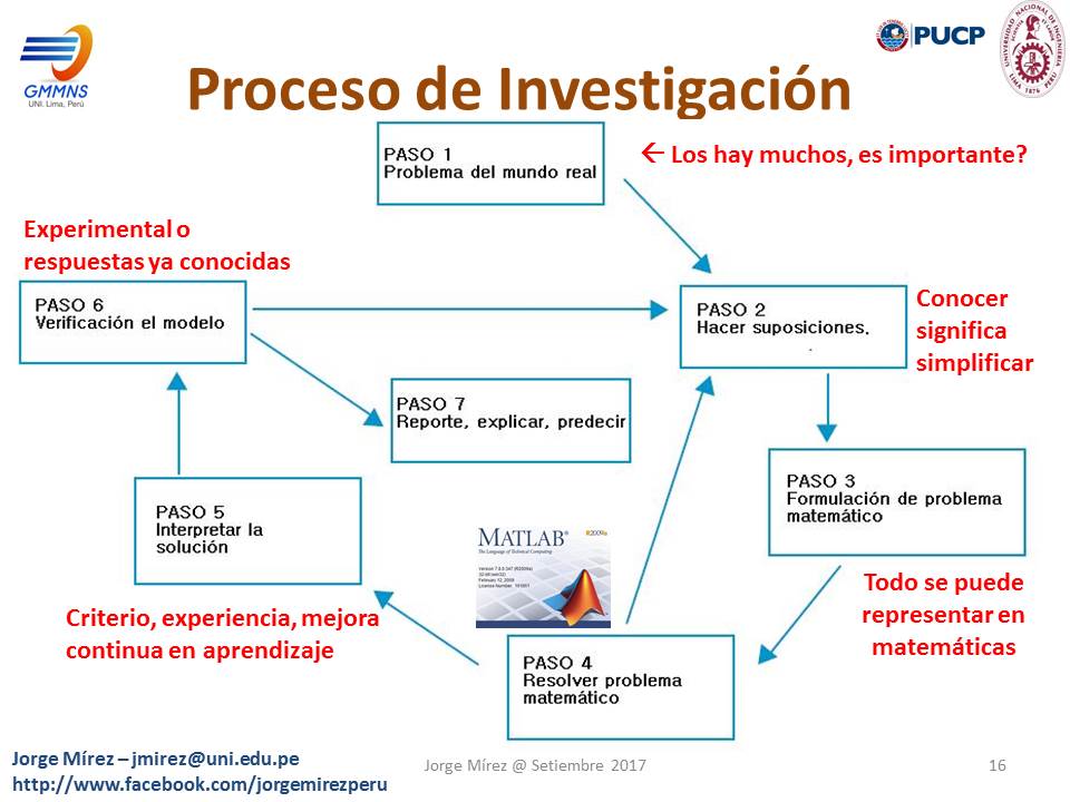
Diapositivas de mi conferencia «Taller de Redacción y Elaboración de Papers» dictado en Pontificia Universidad Católica del Perú -PUCP en Lima, Perú; el miércoles 13 setiembre 2017 en el Facultad de Ciencias e Ingeniería, organizado por AIESEM. Van los JPG de las diapositivas.


El video lo pueden visualizar en mi fanpage http://www.facebook.com/jorgemirezperu o también a continuación:
Mis alumnos y tesistas usualmente me han preguntado como llegar a hacer modelos de una máquina o sistema completo, es decir, de toda una instalación en general. Bueno algunas cosas a considerar les doy a continuación. En primer lugar usar un software de alto nivel, no es que vaya en contra del software libre, sino que estamos hablando a modo de usuarios como ingenieros y científicos que lo menos que deseamos es lidiar con el mismo software; en mi caso uso Matlab/Simulink. En segundo lugar es despiezar el sistema en sus principales componentes, todos ellos se pueden identificar pues utilizan un propio sistema de ecuaciones para ser descritos; por ejemplo: las ecuaciones de un motor eléctrico son diferentes a de una bomba de agua; aún así dentro de cada parte hay sub-partes a considerar dependiendo de la profundidad del problema que se desea abodar. Tercero: se debe comenzar a modelar ecuación por ecuación, sacando el máximo provecho a cada uno de ellas con diferentes valores de entrada y analizando los valores de salida (los resultados), poco a poco se irán simulando cada vez mas ecuaciones y así mismo se irá construyendo el criterio propio de análisis de los resultados para dicho problema. Cuarto: Una vez que se tiene ya varias ecuaciones de los componentes se da el gran paso que es integrar dichos modelos en modelos más grandes que describan los componentes o sistemas; esta integración es en parte todo un arte que se debe cultivar con práctica, paciencia y perseverancia a fin de que los modelos y simulaciones nos arrojen resultados predecibles y comprendibles en base a la experiencia anteriormente ya construída. Quinto: Teniendo ya los modelos de las cosas que deseabamos, un último toque es el «maquillaje» de los resultados, presentándolos lo más interesante y visiblemente adornados a fin de cautivar al público oyente o lector.
Los pasos descritos asumo por los comentarios que me han dado que es algo que casi todos los logramos entender, sin embargo, la principal dificultad radica en (i) el orden de ecuaciones a programar, (ii) la programación en sí de cómo le hago para que la computadora me dé lo que quiero ver y (iii) la integración de varios componentes – varios códigos o programas – en un sólo programa grande, lo cual es algo que puede causar muchas horas de intriga, pasión, duda y contradicción pero que tarde o temprano es un gran alivio y alegría poder lograrlo. Todo esto es como un gran rompecabezas en que hay que estar atento a solución lógica que se presenta ante nuestros ojos en medio del abanico de ecuaciones que tengan que simular.


Página Web: http://jmirez.wixsite.com/mapchota2016
Fanpage: https://www.facebook.com/mapchota2016/
PD: Se invita a los que desean grabarlo, transmitirlo por radio, TV y/o cable el evento.
Link Transmisión en Vivo y en Directo en Español

![]()
![]()
Se invita a todos los que desean participar como Ponentes de este Encuentro. Las reglas son:
-
Las ponencias serán de al menos 15 minutos.
-
Hay espacio para 24 ponencias de 15 minutos.
-
Las ponencias serán transmitidas vía internet por dos canales de YouTube (uno en español y otro en inglés con traductor en vivo).
-
Los ponentes enviarán hasta el 21 de diciembre sus ponencias y CV para ser colocados en el Programa del evento.
-
El modelo del CV en formato Word está disponible en el siguiente link: https://jmirez.files.wordpress.com/2016/12/map-chota-2016_nombreyapellidoponente_cv.docx
-
El modelo de la presentación en formato PPT está disponible en: https://jmirez.files.wordpress.com/2016/12/ppt_mar-chota-2016_autor.pptx
-
Los archivo PPT y Word enviarlo a jmirez@uni.edu.pe
Motivación del Encuentro
Las fiestas de fin de año reúnen a la familia y amigos, para lo cual se da el retorno de estudiantes, académicos y profesionales desde sus centros de estudio, investigación y de trabajo a sus ciudades de origen (en los diferentes ciudades y pueblos a nivel nacional) a pasarla en familia, con las amistades o simplemente es un tiempo de retorno a nuestros lugares de origen.
Este es un motivo especial para reunirnos para conocernos y compartir lo realizado durante el año mediante la conversación y ponencias tanto en lo académico y en las experiencias profesionales sean éstas realizadas en el sector público como privado.
Chota, la Atenas del Norte del Perú, se viste de gala al organizar el MAP Chota 2016 e invita a ser parte de este encuentro entre estudiantes de escuelas, colegios, pregrado y postgrado, académicos, profesores, padres de familia, investigadores, profesionales, organizaciones de base y sociedad en general de fin de año 2016 y hacemos el llamado a todas las ciudades del Perú a que se realicen eventos similares, y hacemos extensivo también a todos los pueblos y ciudades de América Latina.
Durante el MAP Chota 2016 estamos organizando algunas actividades extras: como un compartir; feria tecnológica, artesanal y artística; exposición de fotografías y de libros.
Las seis horas que durará el evento quedará guardado en YouTube y la participación en el evento como Ponente o Asistente es totalmente libre y gratuito. Quedan todos invitados a participar.
Página Web del Encuentro http://jmirez.wixsite.com/mapchota2016

Another example for the control structure used for full-scale converter-based wind turbine concept is shown in Figure. An advantage of this turbine system is that the dc link performs some kinds of control decoupling between the turbine and the grid. The dc link will also give an option for the wind turbines to be connected with energy storage units, which can better manage the active power flow into the grid system—this feature will further improve the grid supporting abilities of the wind turbines. The generated active power of the WTS is controlled by the generator side converter, whereas the reactive power is controlled by the grid side converter. It is noted that a dc chopper is normally introduced to prevent overvoltage of dc link in case of grid faults, when the extra turbine power needs to be dissipated as the sudden drop of grid voltage
Source:
Frede Blaabjerg and Ke Ma “Future on Power Electronics for Wind Turbine Systems” IEEE Journal of Emerging and Selected Topics in Power Electronics, Vol. 1, No. 3, September 2013

The control methods for a DFIG-based WTS are shown in Figure. Below maximum power production, the wind turbine will typically vary the rotational speed proportional with the wind speed and keep the pitch angleθ fixed. At very low wind speed, the rotational speed will be fixed at the maximum allowable slip to prevent over voltage of generator output. A pitch angle controller is used to limit the power when the turbine output is above the nominal power. The total electrical power of the WTS is regulated by controlling the DFIG through the rotor side converter. The control strategy of the grid side converter is simply just to keep the dc-link voltage fixed. It is noted that a trend is to use a crowbar connected to the rotor of DFIG to improve the control performance under grid faults.
Source:
Frede Blaabjerg and Ke Ma “Future on Power Electronics for Wind Turbine Systems” IEEE Journal of Emerging and Selected Topics in Power Electronics, Vol. 1, No. 3, September 2013

The second important concept that is popular for the newly developed and installed wind turbines is shown in Figure. It introduces a full-scale power converter to interconnect the power grid and stator windings of the generator, thus all the generated power from the wind turbine can be regulated. The asynchronous generator, wound rotor SG (WRSG) or permanent magnet SG (PMSG) have been reported as solutions to be used. The elimination of slip rings, simpler or even eliminated gearbox, full power and speed controllability as well as better grid support ability are the main advantages compared with the DFIG-based concept. The more stressed and expensive power electronic components as well as the higher power losses in the converter are, however, the main drawbacks for this concept.
Source:
Frede Blaabjerg and Ke Ma “Future on Power Electronics for Wind Turbine Systems” IEEE Journal of Emerging and Selected Topics in Power Electronics, Vol. 1, No. 3, September 2013

This wind turbine concept is the most adopted solution nowadays and it has been used extensively since 2000s. As shown in Figure, a PEC is adopted in conjunction with the DFIG. The stator windings of DFIG are directly connected to the power grid, whereas the rotor windings are connected to the power grid by the converter with normally 30% capacity of the wind turbine. In this concept, the frequency and the current in the rotor can be flexibly regulated and thus the variable speed range can be extended to a satisfactory level. The smaller converter capacity makes this concept attractive seen from a cost point of view. Its main drawbacks are however, the use of slip rings and the challenging power controllability in the case of grid faults—these disadvantages may comprise the reliability and may be difficult to completely satisfy the future grid requirements
Source:
Frede Blaabjerg and Ke Ma «Future on Power Electronics for Wind Turbine Systems» IEEE Journal of Emerging and Selected Topics in Power Electronics, Vol. 1, No. 3, September 2013

The use of low-speed permanent-magnet generators that have a large number of poles allows obtaining the dc sources from the multiple wounds of this electrical machine, as can be seen in Figure. In this case, the power-electronic building block (PEBB) can be composed of a rectifier, a dc link, and an H-bridge. Another possibility is to replace the rectifier by an additional H-bridge. The continuous reduction of the cost per kilowatt of PEBBs is making the multilevel cascaded topologies to be the most commonly used by the industrial solutions. This as one alternative to multinivel conversors.
Source:
Juan Manuel Carrasco, Leopoldo García Franquelo, Jan T. Bialasiewicz, Eduardo Galván, Ramón C. Portillo Guisado, Ángeles Martín Prats, José Ignacio León and Narciso Moreno-Alfonso “Power-Electronic Systems for the Grid integration of Renewable Energy Sources: A Survey”. IEEE Transactions on Industrial Electronics, Vol. 53, No. 4, August 2006

A simple block diagram of a hybrid power system is shown in Figure. The sources of electric power in this hybrid system consist of a diesel generator, a battery bank, a PV array, and a wind generator. The diesel generator is the main source of power around the world. The output of the diesel generator is regulated ac voltage, which supplies the load directly through the main distribution transformer. The battery bank, the PV array, and the wind turbine are interlinked through a dc bus. The RTU (Remote Terminal Unit) regulates the flow of power to and from the different units, depending on the load. The integration of a RTU into a hybrid power system is important to enhance the performance of the system. The overall purpose of the RTU is to give knowledgeable personnel the ability to monitor and control the hybrid system from an external control center. Since the hybrid systems of interest in this research are located in remote areas, the ability for external monitoring and control is of utmost importance. The RTU is interfaced with a variety of sensors and control devices located at key locations within the hybrid system. The RTU processes the data from these sensors and transmits it to a control center. In addition, the RTU is also capable of receiving control signals and adjusting parameters within the system without the physical presence of the operating personnel.
Source:
Richard W. Wies, Ron A. Johnson, Ashish N. Agrawal and Tyler J. Chubb «Simulink Model for Economic Analysis and Environmental Impacts of a PV With Diesel-Battery System for Remote Villages» IEEE Transactions on Power Systems, Vol. 20, No. 2, May 2005
Blog in ENGLISH

Compra/Buy – Haz una donación/Make a donation

Dear reader, if you wish to make a donation or are interested in any information or code, please contact me (e-mail: jmirez@uni.edu.pe). Donations will allow you to continue studying and researching, and also to provide more information on this blog. My PayPal account is jorgemirez2002@gmail.com or if it is by bank transfer write to my email jmirez@uni.edu.pe. Any amount of money is welcome. Thank you.
Estimado lector, si desean hacer una donación o le interesa alguna información o código, favor ponerse en contacto con mi persona (e-mail: jmirez@uni.edu.pe). Las donaciones va a permitir seguir estudiando e investigando, y además, el poder brindar más información en este blog. Mi cuenta en PayPal es jorgemirez2002@gmail.com o si es por transferencia bancaria escribirme a mi correo jmirez@uni.edu.pe. Cualquier cantidad de dinero es bienvenido. Gracias.
Datos Generales
Good day. My full name is Jorge Luis MIREZ TARRILLO.
I am Peruvian and live in Lima, capital of Perú in South America.I am Mechanical Electrical Engineering, MSc Physics and Dr. Physics (title doctoral thesis: Control, Optimization, and Management of Microgrid Current Direct)
Too, actually job as Principal Professor in Faculty of Oil, Gas and Petrochemical Engineering of Universidad Nacional de Ingeniería (National University of Engineering) in Lima – PERU (Courses: Modern Physics, Differential Equations and Research's Methodology)
My subjects of my interest are control, signal processing, optimization, simulation, biomedical research, smart grid, microgrid, water.
I have experience in Matlab/Simulink programming, biomedical equipment, electrical systems, renewable energies, microgrids, saturated steam systems 100 psi and organizing academic events.
Comentarios Recientes
Elementos que compon… en J506: Los elementos de un paqu… Dr. Jorge Mírez en Message by IEEE Community Dr. Jorge Mírez en J546: Simulación de campos mag… jose luis huayanay v… en Message by IEEE Community Cesar Aviles en J546: Simulación de campos mag… Dr. Jorge Mírez en J518: La herramienta pdetool d… Dr. Jorge Mírez en J496: Simulación en Matlab/Sim… Raúl Barrios Elizarr… en J496: Simulación en Matlab/Sim… jose luis huayanay v… en J518: La herramienta pdetool d… MSc. Jorge Mírez en J281: La Rosa de Vientos: Frec…

Debe estar conectado para enviar un comentario.